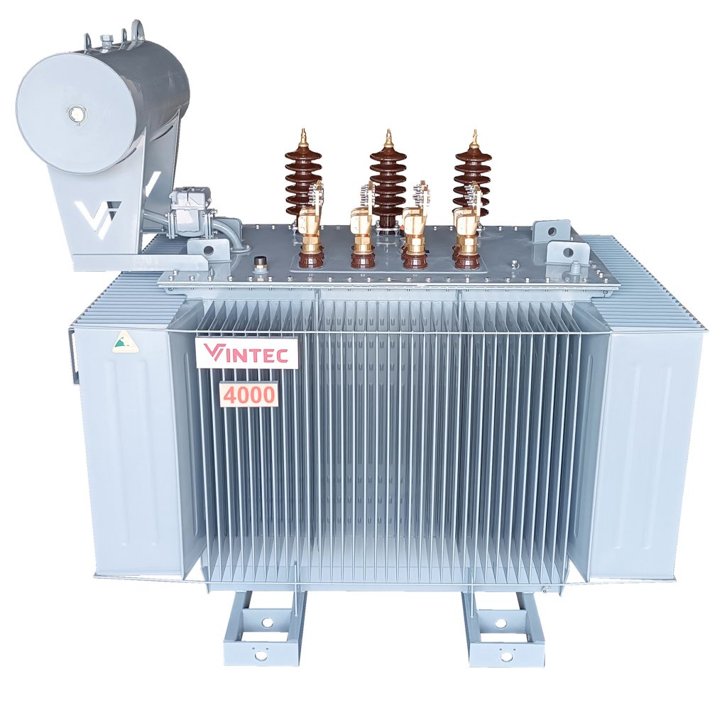
The Structure of Three Phase Transformers
Transformers are essential electrical devices in power transmission and distribution systems, delivering electricity to consumers. To meet the demand for transmitting electricity over long distances, transformers with sufficient power are required. This is why three-phase transformers were developed. So, what are three-phase transformers, and how are they structured? Let’s find out through the following article.
1. What is a Three Phase Transformer?
A three-phase transformer is a static electrical device designed to transmit energy or exchange alternating electrical signals between electrical circuits through Faraday’s electromagnetic induction phenomenon. Three-phase transformers play a crucial role in power transmission systems. These devices are widely used in industrial settings to generate, transmit, and distribute electrical energy. They are installed in places with high electricity consumption, such as office buildings, apartments, hospitals, and transformer stations.
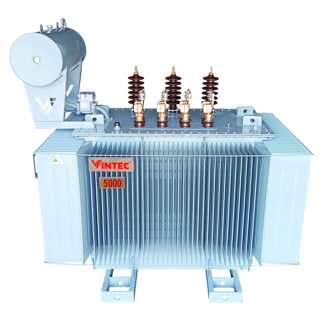
2. Structure of Three Phase Transformers
To be used in large power grid systems, three-phase transformers are relatively complex in design. The structure of a three-phase transformer includes main components such as the core, winding, transformer casing, and other auxiliary parts.
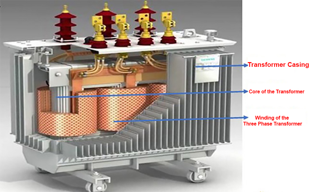
2.1. Core of the Transformer
The core consists of the limb and yoke. The limb is where the winding is placed, while the yoke connects the limbs to form a closed magnetic circuit. The transformer core is made up of multiple thin sheets of electrical steel (silicon steel) insulated from each other. These are typically made of good conductive materials.
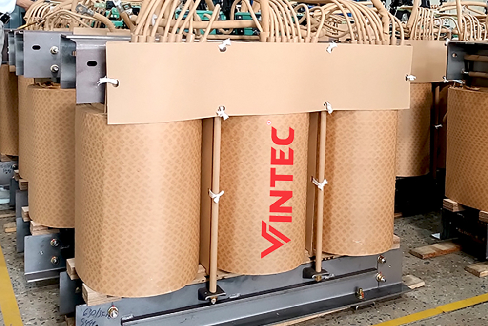
2.2. Winding of the Three-Phase Transformer
The winding is usually made of copper or aluminum wire wrapped with insulation. Its role is to receive energy input and transmit output energy. The primary coil (N1) receives energy input (connected to the AC circuit), while the secondary coil (N2) transmits output energy (connected to the load). The number of turns in the two coils may differ, depending on the transformer’s task, with N1 > N2 or vice versa.
2.3. Transformer Casing
The casing material varies depending on the type of transformer and may be made of plastic, wood, steel, cast iron, or sheet metal. It serves to protect the internal components of the transformer.
2.4. Auxiliary Parts of the Three-Phase Transformer
To complete the structure of a three-phase transformer, several important devices cannot be overlooked, including:
Transformer oil. Insulation materials. Transformer base. Voltage measuring instrument.
3. Operating Principle of Three-Phase Transformers
The operating principle of a three-phase transformer is quite simple. It operates based on two physical phenomena: Electric current flowing through the conductor creates a magnetic field. The varying magnetic flux within the coil induces an electromotive force. Understanding the operating principle of the transformer makes it easier to grasp the working process and ensure the efficient operation of the three-phase transformer, maintaining its rated power.
4. Types of Three-Phase Transformers
Generally, transformers are classified based on voltage levels, core materials, winding arrangements, usage, and installation location. Here are the most common types of three-phase transformers used in the market today:
Enclosed Three-Phase Transformers Open-Type Three-Phase Transformers Dry-Type Transformers Amorphous Transformers
4.1. Enclosed Three-Phase Transformers
Enclosed three-phase transformers dissipate heat through expanded fins. When the temperature rises inside the transformer, these fins expand, allowing air to blow directly through them to dissipate heat.
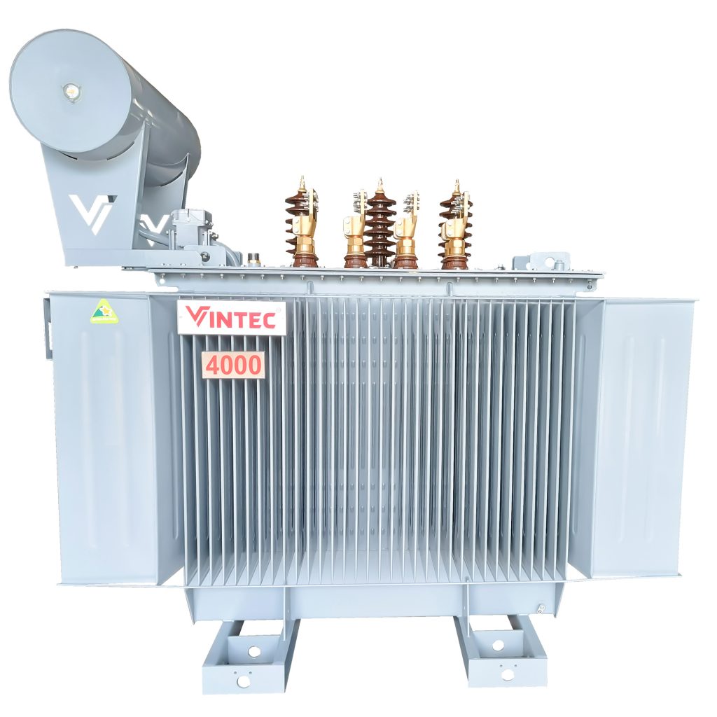
4.2. Open-Type Three-Phase Transformers
Open-type transformers are devices that transform the voltage of alternating current from one level to another. Open-type three-phase transformers have auxiliary oil tanks. They are distribution transformers with input voltages of 35kV, 22kV, 10kV, output voltages of 0.4kV, and immersed in standard insulating oil.
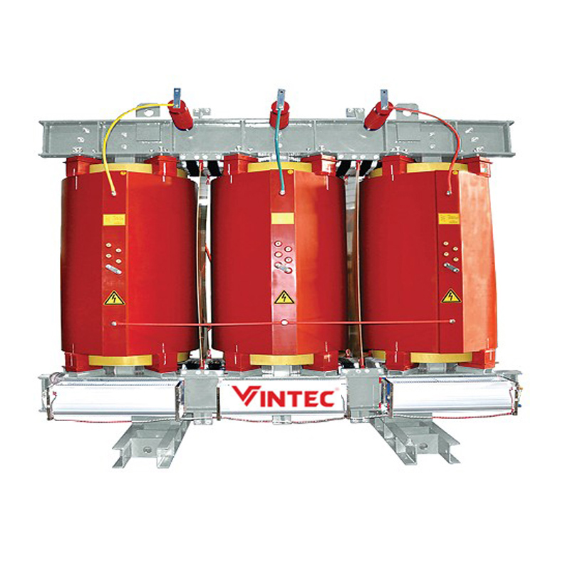
4.3. Dry-Type Transformers
Dry-type transformers do not use any liquid insulation. Instead, their coils or cores are immersed in a liquid. Instead, the coils and cores are held in a sealed tank pressurized with air.
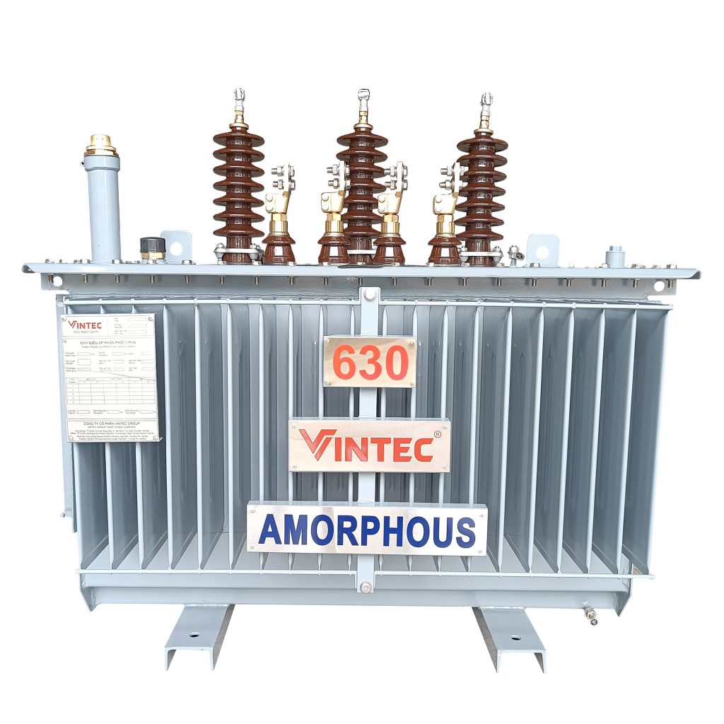
4.4. Amorphous Transformers
Amorphous transformers are energy-saving transformers installed on power grids. The core of these transformers is made of non-oriented iron-silicon metal. The typical material (Metglas) is an alloy of iron with boron, silicon, and phosphorus in the form of thin sheets (e.g., 25 µm) rapidly cooled after melting. These materials have high permeability, low magnetic resistance, and high dielectric strength. High resistance and thin sheets result in low losses due to eddy currents when exposed to alternating magnetic fields. On the other hand, amorphous alloys have lower saturation induction and generally higher friction than conventional crystalline iron-silicon electrical steels.
Amorphous Transformers

